TR-808 White Noise
This post originally appeared on the SS-30M blog on 08/08/21
As I continue to ponder the wisdom of making my own 808 snare drum module, the ticklish matter of white noise requires my attention. Oh, and today is 808 day!
Transistors' Histories
The tickling mostly comes from the unobtanium transistor that Roland used. As explained by Roland's founder Ikutaro Kakehashi in 808: The Movie there was a rejected part that they specifically used to get the exact right kind of white noise. No longer available because the transistor manufacturing was improved, there is a no way to rebuild 808s like the did back in the day. Or is there? I see there's someone in Spain selling genuine spares, but with a price with shipping getting on on for £50 something else is needed.
| Matsushita 2SC828R from https://secretlifeofsynthesizers.com - Note the white dot on top indicating it was selecetd for the specific quaility of its noise. |
Some work has been done on testing this story's truth and whilst it remains a controversial topic there must be something in this tale. Most of what follows comes from the Secret Life Of Synthesizers (SLOS) blog. In the schematic Q35 is labelled '2SC828 RNZ' - NZ meaning noise. Indeed, the particular transistors used are, according to the service manual, "selected noise", or 'selected for noise'. Spare parts come in a bag labelled "NZ select".
The Parts List part number is 2SC828(R), with R posibly standing for Rejected, although there are different rankings for hFE - Q, R & S - and it it's far more likely that this is the R referred to. The photo of real 808 transistors from the SLOS blog posts are labelled 'R', and it seems unlikely that the manufacturer (Matsushita - Panasonic) would go to the trouble of adding a different R to rejected parts. It's also possible to find photos of other identical parts with Q and S labels. In fact the photo of a 2SC828 in situ on the SLOS site is labelled S. So, we can pretty much ignore that 'R'!
In conclusion, the SLOS posts are sure that the 2SC828 transistors were selecetd for a particular character of noise. My guess is that that were carefully selecting by some sort of measurement and eventually found that they were no longer getting the character they wanted. The other revealation of this investigation was that not all 808s were fitted with 2SC828 anyway! Some had 2SC536 and others 2SC945. According to SLOS, both of these sound closer to the selected 2SC828 than stock 2SC828s. What was all the fuss about then? It's this discovery that will lead many to assume that the story in 808 The Movie was a myth. The 2SC945P parts are used across the 808 as the default NPN transistor, but the good sounding ones were still selected. In the end the SLOS advise us to find a 2SC945P which sounds as good as the original, because they are out there.
What does it sound like though? SLOS say the selected parts are "smooth" compared to others. The fourm user at GearSpace called Tirez is the SLOS blogger and said he was going to produce some example recordings - but aperently never did, or didn't share them. In the end it might only be possible to decide by buying an 808, or buying a genuine spare part. The cheaper way might be to compare the finished sound in its shaped form to a good example of the 808 - on my TR-6S for example.
A Lot More
All very interesting, but there is somethine else bugging me about the white noise circuit. In the schematics there are two noise generator circuits. The one wired up to the pink noise and fully labelled is the original, but there is another off to the side and below with an arrow to it labelled "6 lot ~". This indicates that the original schematic was used only for the first 6 lots.
A Lot Better?
Turning to the "Design Changes & Improvements" section we find change number 5. This improvement is "Effectivce With Serial Number" 010600 and describes the changes to the white noise circuit above. '010' refers to the second month of production, the first month being November 1980 and numbered '000'. And, of course '600' refers to the number of units produced, indicating that each lot was of 100 units.
The "Part Affected" is given as "Noise Generator (IC24)" and then the changes are listed.
- R129 330K->short
- R311 330K->100K
- R127 4.7K->10u (C200)
- C202 0->22p
This corresponds to the schematic changes - with one mistake, which we'll get to later.
PCB Plan B
In addition, a note on the schematic indicates that C202 is "surface mounted". A look at the Main Board PCB layout shows that C202 actually has its own location and is not "surface mounted". Early units presumably had this part soldered on to the legs of R130, but they then went on to change the PCB to accommodate the new cap.
No Earthedly Reason
Those were the changes, but what did they do and why was it needed? The Reason is stated as follows:
"Variations in UPC4558 bias current are transformed to 1/2 IC24 output as an offset reducing gain margin".
I'm going to rewite that slightly to make it clearer: 'Variations in the bias current of the op-amp are transfered to the output as an offset DC voltage, reducing gain margin'.
Variations in op-amp input bias currents are indeed a problem. Especially back then, production tolerances were not as good, so the inputs could end up drawing slightly different amounts of current, for the same input voltage. No values are given, but the resultant DC offset voltage at the output would then be amplified by the feedback divider. DC offset can obviously offset the output AC signal far enough to clip it into the rails so that would need to be dealt with. It seems that this was not a problem in development, but once a few hundred units had been made the calibration of the white noise appears to have been causing some grief. The required output is 130mV RMS, which is way below the +/- 15v rails of the op-amp and yet this DC offset was too much of an issue.
Loops, I Did It. A Gain.
It's hard to be too certain what the impact of this DC offset was, considering the limited information given, but the final part of the reason for the change is "reducing gain margin". I had to go back to op-amp school to recall what that means, but now I think I know what was happening. In short (very short!) the gain margin is a measure of how close the closed-loop gain is to the open-loop gain. Loop gain is actually the difference between open and closed loop gain and the gain margin is how close they are to meeting. As the open-loop gain reduces with increasing frequency this is more likely to occur than you might first think - open-loop gain being assumed as infinite for theoretical purposes. The uPC4558 has a nicely behaved open-loop frequency response for audio use, but the closed loop gain of the circuit is high enough to start causing some concern above 10kHz.
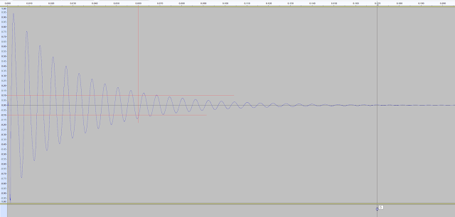
 |
| uPC4558 open-loop gain with the midpoint of the Noise Generator closed-loop gain (red) |
As the gain margin required can only be inferred, let's assume some of the units needed a bit more gain to achieve that 130mV RMS (provied by the trimmer) and that some ICs created more of a DC offset at the output than the Roland designers had allowed for. Well, in that case there is likely going to be no gain margin left. Note, there is little question of the circuit becoming unstable and self oscillating here. The phase margin should not be enough to result in 180 degree difference between inverting and non-inverting terminals. At least, I don't think so... Setting the correct level of noise would have become challenging for the test technicians though.
Decouple DC
Roland need to get rid of that problem, so what was the solution? Simply stated: "Decouple DC". The original design works fine in ideal conditions, but that DC offset really seemed to push the noise signal out of whack and make calibration impossible, or just maybe it was compressing the higher freqencies too much and taking the flat spectrum of the white noise and skewing it too much? Well, maybe, but as we'll see that seems to not have been such a concern. Anyway, decoupling DC is the remedy, and now we can start to analyse each change.
Firstly, the decoupling of DC is put into affect by the change "R127 4.7K -> 10u (C200)". With this change, the output DC offset is not removed, but it is limited to unity gain. C200 acts an open circuit for DC and so the offset voltage is no longer divided and no longer amplified. This assumes that the unamplified DC offset was low enough not to be a problem. The AC signal is now going to see a reactive capacitance in place of the resistor, but this 10uF part will be quite low impedance for most audible frequenices and the 22K trimmer can presumabley be adjusted to make up the 4.7K resistance lost. Problem solved! So, why were three more changes required?
The second change is fairly staright forward to explain. "R311 330K->100K" changes the input filter. Looking at it another way though, R311 is placed after the AC coupling capacitor C31, 1uF, to provide a current source for the non-inverting input. Good design practice is to match the RC value of both inputs in an AC coupled non-inverting op-amp (see How To Bias An Op-Amp link below). So, the Roland team decided to assume that the trimmer is around 10K and multiplied that by 10uF. To match that R311 had to change to 100K, which multipied by 1uF gives the same RC of 0.1. Of course, the trimmer could be any value from 0 to 22K, but they had to choose something, and so they have it close to the mid-point of 11K. I can only think the 22K was chosen to achieve the right gain for most transistors, so with the 4K7 the correct divider would be around 15.7K, but now I'm splitting hairs.
The third change is of a similar purpose to the second. R129 is simply removed and shorted out. Note though that the resistor value is typed incorrectly in the changes! This could be confusing as 330K is the sames as R311. In fact it was 300K, according to the schematic and this makes more sense. The bias point of both inputs was to ground - through R311 for the non-inverting input and through R129, TM4 and R127 for the inverting. 300K + 22K(variable) + 4K7 is a good enough match to 330K so that's what they went with. Of course, once the coupling of the non-inverting input was changed to AC, and R311 changed to 100K in an RC ,atching situation, R129 was surplus to requirements.
The fourth and final change does not seem to be required! The solution of decoupling DC from the inverting input has been implemented by the preceeding changes, as I described. The capacitor C200 changes the input biases, which leads to the changes in resistors. And yet, Roland saw fit to add C202, 22pF in parallel with the feedback resistor R130. This really does seem to only be required in order to attenuate the higher frequencies and maybe ensure the phase margin is not exceeded. There is no mention of this phase margin, but the gain margin will be improved, so I can only conclude that decoupling DC was not enough.
Clone Worries
The fact is though, whether the decoupling and the filtering of C202 are required for any particular tansister and op-amp is not in question now. The clones I have seen do not copy the revised design, probably because they do not need to worry about the variations in bias currents with newer op-amps. But by missing out the capacitors they have altered the tone of the white noise. Altered it back to what the designers originally intended, yes. But, altered it away from the sound of what most actual 808s sound like. Note that units before lot 6 were probably modified to include these changes too. Perhaps only a few, or a few hundred, were released without the mods.
None of the clones use the fabled 'NZ' transistors, selecetd according to a process which we can only guess at, though. There's only so far you can go, it seems. Hand sorting transistors and binning the rest is costly, afterall. Still, the determined DIYer can be more generous with their time and rejects.
For the sake of a couple of components it seems better, to me, to inlcude C202 and possibly C200 too to get as close as possible to the original sound - correct transistor or not.
Perhaps I will have to try this before judging anyone else though...
- https://www.facebook.com/808themovie/
- https://secretlifeofsynthesizers.com/the-strange-heart-of-the-roland-tr-808/
- https://secretlifeofsynthesizers.com/roland-tr-808-noise-transistor-update/
- https://gearspace.com/board/electronic-music-instruments-and-electronic-music-production/1204244-808-defective-transistors.html
- MAS.836 HOW TO BIAS AN OP-AMP


Comments
Post a Comment