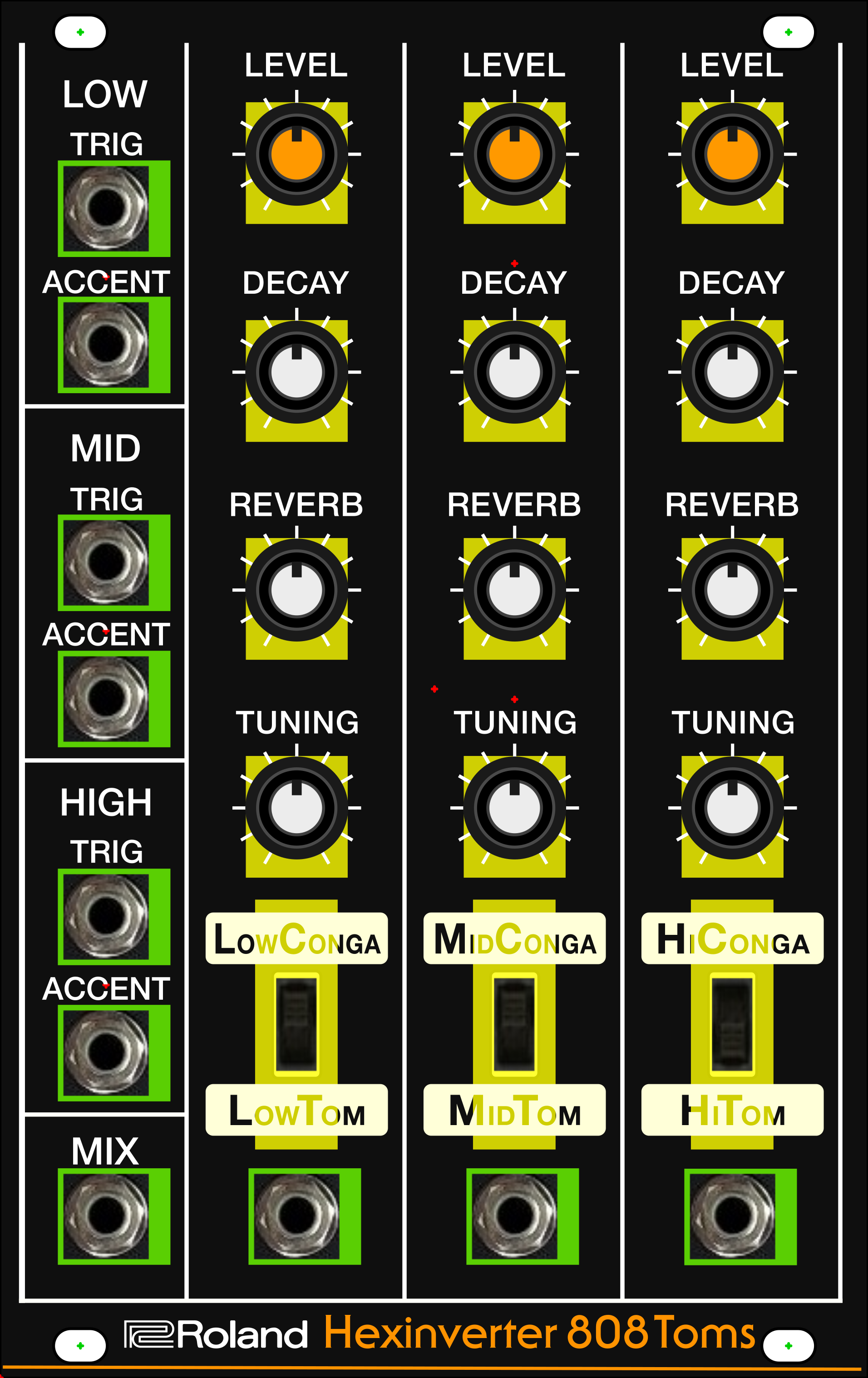
AteOhAte Toms
This post was originally published on the SS-30M blog on 18th July 2020
Updates are coming out of order now, but not to worry. This is the most recent thing I've been working on and it has some relevance to the odessey that is the SS-30M. The tl:dr here is that I did another Schaeffer panel and I have embraced crimped connectors at long last.
One of my other side projects to the SS-30M has been Eurorack modular drums. Last year it was the Pharmasonic SY-1, a clone of the Pearl Syncussion.

And the year before that I completed a DIY build with my own panel design. That Hexinverter Eletronique TR-909 Rim Shot and Hand Clap clone was documented in this post about the Nein Oh Nein.

I got the PCBs for the NeinOhNein in 2017 and at the same time grabbed another set of Hexinverter boards for the AteOhAte Toms. I started this in 2018 in parallel with the NeinOhNein but the mechanical design was intense.
Knobs
Like the NeinOhNein, I wanted to go with an authentic Roland TR look. For that module I'd bought some knobs from the guys doing the Nava 909 clone, but I wasn't happy with the options for TR-808 controls. Original 808 parts are not only expensive and hard to find, but the knobs are built into the pots. Not to worry though! Roland brought out their own 808 clone in 2017, the TR-08.


Look at those dinky little knobs! These are exactly what I need. Small, and, better yet, I knew Roland would have spares that I could probably buy. So, that's what I did. a few e-mails and a phone call later and I'd got a bunch of perfect knobs on the way from Japan.

And handily the knobs fit a standard 9mm D-shaft.

Splendid. Knobs in the bag. What next?
Pots
Whilst I was waiting for the knobs I built up the boards and I'd ordered some pots and switches already. I wired up each of the three boards in turn to a temporary control panel built on a prototype board.

As you can see though, one of the pots is a very much bigger size to the others. The AteOhAte design calls for 2x100KA, 1x1MB and 1x 500B. That 500B was a problem. The only thing I could get with a D-shaft was a dual-gang 1K part wired in parallel.
Anyway, I set about trying to design around this larger pot and it was no fun.
Ate Oh Hate
I wasn't that happy with the size of the NeinOhNein Rim Shot and Hand Clap module I made. It's just hard to make a narrow module and not make it extremely deep. The Hexinverter boards were designed for wiring of controls and no control board is provided or specific layout is mandated. Although sized for Eurorack they can be used for 4U, 5U or whatever you want. ReSynthesis made two panels for the Toms, but it's an arbitrary layout. There's a single panel, but the triple is 22HP.

The two issues I had with this panel were the deisgn not matching the original 808 aesthetic and the size. 22HP isn't huge, but I wanted more space in my drum rack.
So, what about that design I started with?
To begin with, I had a 22HP design in mind, because I figured I needed that much space. Then I started to optimise and got to a 17HP design.
The problem was the oversized switches and those dual-ganged 1K pots.

At this point I simply stopped. I wasn't happy with the design and I couldn't work out how to make it better.
I eventually returned to the project 18 months later, in 2019, and looked again for a better 500 Ohm potentiometer option. This time I found the Bourns PTD902-2015FB10.

This layout wasn't arived at easily though. What you see above is carefully worked out with layers of sub-panel and Veroboards to hold it all.

I wasn't sure if this woud all fit though. So, I went down a rabbit hole of 3D modelling. This has got much easier since Windows 10 and support for 3D printing.
Making a 2D shape 3D is easy. Here's the sub-panel that the knobs and switches attach to to make then sit at the right height.

And a lot of parts are now available already modelled, like these switches.

And even the exact Thonkiconn jack sockets I wanted.

But some things I had to make myself, like the knobs. It took a lot of figuring out. I enjoyed it though and the results were satisying.


Mostly though, I had shown that things would fit together as I thought they would when it was all in 2D. Next though I wanted to mock this thing up before going to Schaeffer putting money down. But first let's look at the Schaeffer panel.
Schaeffer Panel
Schaeffer? They too have 3D renders now.


And not only that, you can export the files as .stp, a 3D format. I was able to use this feature to match up my Front Panel Designer file with the stuff I was doing in Inkscape in one 3D model. As I said though, I still need a mock-up before comitting to a panel. I'm cautious.
Mock-up
As with the NeinOhNein module I got help from my friend with access to laser cutting. I got both a front-panel and the sub-panel designs cut.


Now I can put together the whole thing and double, or is that triple?, check the design.
Oh, wait! I forgot that I had another piece cut by my laser buddy.
The Veroboard for the pots has to be pretty accurately cut and drilled because it has fixing holes that must match up to the AteOhAte PCBs. I had the outline cut onto a piece of MDF and use that as a template to cut the Veroboard and drill the holes in it.


This made a tedious job much easier and gave me piece of mind that things would line up and fit neatly without any squeezing.
Here's the pots Veroboard mated to the sub-panel assembled with the switches in place too. Note that the Bourns 500R pots are right-angled and need their own Veroboard. It's pretty close to the switches but not touching.


The next step was the Veroboards that hold the jack sockets. I preferred to use boards to wiring each one individually for a couple of reasons. Firstly the number of wires is reduced because I can use the tracks for common ground and don't have to solder so many fiddly jumpers from socket to socket. Secondly, I needed to wire up the Mix output and having a board made that easier too. Thirdy, the jack sockets really are PCB mount and wiring them is unsatifying and messy - not that the size of these is inportant for the design. More Veroboards.


This still leaves the wiring to do, but this is what it looked like as a mock-up.

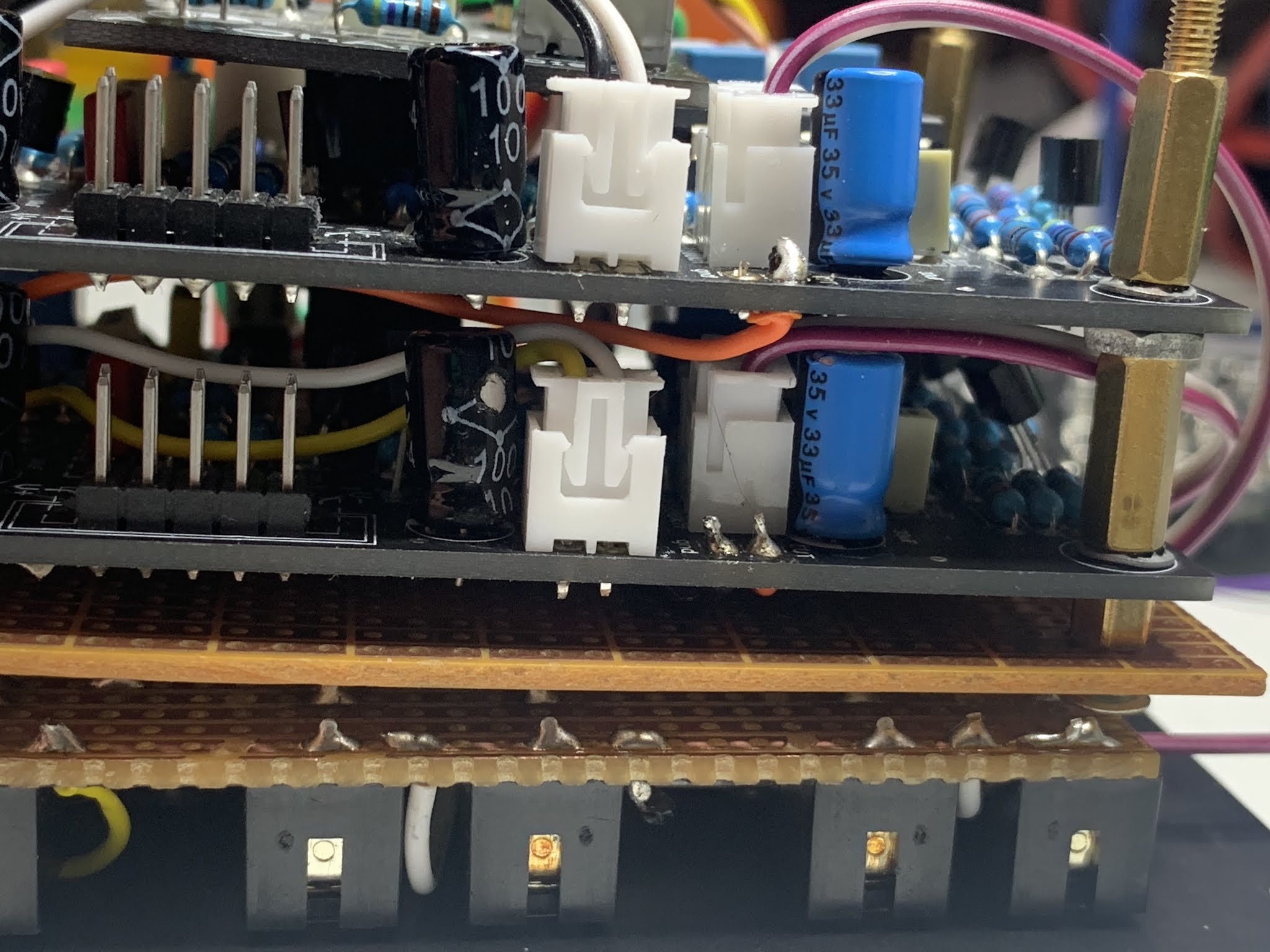
Wiring
Finally I come to something more relevant to the SS-30M. My favourite topic in fact. Wiring.
Each board of AteOhAte Toms has twenty wires so that's sixty in total!

As I've used boards for the sockets, the earths can be rationalised and the same for the Reverb ground. In turns out that only two wires are needed for Level, But still... A lot of wires.
I found that desoldering the wires and cleaining the holes after the test wiring I'd done was also a chore on these boards. Small holes. This led me back to an old idea - crimp connectors!
When I planned the connectors for the MIDI inteface I noted how expensive crimp tools are. Now though? Now it seems that the popularity of Arduino projects has shifted the market and I was able to get a tool and box of connectors off Amazon for half the price that crimps seemed to be a few years ago,
As the set came with a colour coded ribbon cable I used that for a lot of the wires and was quickly squeezing out crimped wires.

As for the SS-30M, I can see me using these connectors for the font-panel, instead of all the point-to-point soldered joints.
Assembley was still not easy, despite the careful design. One screw in particular had to be tweezered into place; pushed into position by a screwdriver which accesses it through a hole specially drilled in the pots Veroboard; held ready whilst the main boards were jostled together into the panel and then screwed in. I practiced doing this with the mock-up.
 |
| Screw held in place between the pots Veroboard and the sub-panel |
 |
| Triggers Veroboard aligned with pots boards and screwdriver holding screw in place. |
 |
| Screw fixed to (mock) front-panel, securing sub-panel |
Schaeffer Panel
Wiring sorted out, it was time to pull the trigger on the front-panel.


Final Assembley
And so, at lomg last, to assembley!
 |
| Trigger/Accent board offered up to front-panel |
 |
| Pots Veroboard with crimped connectors wired in |
 |
| Pots boards in place on front-panel |
 |
| Detail of sub-panel fixed to front-panel and switch bolted to sub-panel. |
 |
| First AteOhAte toms board in place |
 |
| First AteOhAte board wired in |
 |
| Side view of trigger, pots and first two AteOhAte boards. |
 |
| Assembley Complete! |
 |
| Tightly packed |
AteOhAte Toms
And here it is!


Comments
Post a Comment